
To specify a dip tube for cosmetic pump packaging, define its length from an agreed measurement point, internal and external diameters, material, and end-cut geometry. Then confirm where the inlet sits inside the assembled bottle and test dispensing with the actual formula through to the end of use. Bottle capacity or external height alone cannot establish the correct tube specification.
For buyers, cosmetic pump dip tube selection is a pump–bottle–formula matching decision. The tube must connect securely to the pump, provide an open path for product, and reach a useful pickup position without an unintended bend or blocked inlet. A complete specification connects those requirements to a drawing and an approved sample.
What a Dip Tube Does in a Cosmetic Pump
A dip tube connects the pump inlet to product deeper inside the bottle. During the pump’s refill cycle, product enters through the tube and moves into the pump chamber. Topfeelpack’s explanation of spray pump components and operation identifies the suction tube as part of this fluid path.
The tube does not independently determine output per press. Pump design, formula behavior, and assembly also matter. For tube approval, focus on whether product can reach the pump consistently and how much remains when normal dispensing stops.
Start with the exact bottle and pump combination. When reviewing Topfeelpack’s lotion bottle range, request the assembly drawing for the shortlisted model rather than selecting a tube from nominal bottle volume.
Define Dip Tube Length Before Comparing Quotes
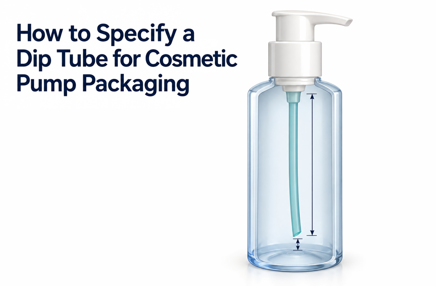
“Dip tube length” needs a clearly labeled reference point. A dimension measured from a gasket plane to the tube tip is different from the cut length of the loose tube, part of which may fit inside the pump connection.
The Cary Company’s dip tube measurement guide measures an assembled sprayer from the top of its gasket to the bottom of the tube. Use that as an example of an explicit convention; confirm the convention on your supplier’s drawing before approving a dimension.
Ask the supplier to distinguish:
- Loose tube cut length: The tube’s end-to-end length before insertion.
- Insertion depth: How far the tube enters its pump connection.
- Assembly reference-to-tip dimension: The distance from the agreed pump or closure reference to the defined tip point.
- Installed inlet position: Where the opening sits relative to the bottle’s internal base.
For an angled cut, specify whether the dimension ends at the longest tip or another defined point. Include units and tolerances. A number without these details can produce different assemblies that appear to meet the same purchase order.
Use Internal Geometry to Establish the Starting Length
For a straight, vertical arrangement, a useful starting relationship is:
Reference-to-tip reach = internal distance from the installed reference plane to the local bottle base − intended tip clearance
This describes installed geometry, not necessarily loose tube cut length. The supplier must account for its pump connection and measurement convention.
For illustration only, if the internal distance is 120 mm and an engineering trial uses 2 mm of tip clearance, the starting reference-to-tip reach is 118 mm. These are hypothetical dimensions, not a recommended clearance or production specification. An angled opening also extends above its lowest tip, so the complete inlet position still needs evaluation.
Review dimensional extremes as well as the nominal drawing. Ask whether a longer permitted tube could press against a shallower permitted bottle, and whether a shorter permitted tube could leave an excessive gap in a deeper bottle.
Match the Tube End to the Bottle Base
The internal base can differ substantially from the bottle’s exterior. A raised center, curved transition, or recessed area can change where product collects and where the tube opening sits.
The Cary Company explains that a tube sitting flush against the bottom can obstruct dispensing and describes an angled cut as one way to avoid that contact. It also distinguishes rigid tubes for thicker products from thinner sprayer tubes that may deliberately bend toward the container wall. These are design approaches to evaluate, not interchangeable rules for every cosmetic pack.
| Bottle or assembly feature | What to examine | Approval question |
|---|---|---|
| Flat internal base | Clearance and open inlet area | Does the inlet remain open across assembly tolerances? |
| Raised central base | Product collecting around the raised area | Can the inlet reach the usable product near the end of use? |
| Curved or sloped base | Tube contact and pickup location | Does the tip settle into a repeatable position? |
| Flexible tube with a planned bend | Bend location and inlet direction | Does assembly preserve the intended bend without kinking? |
| Narrow or asymmetric bottle | Tube path during insertion and closure fitting | Can production assembly reproduce the approved position? |
Do not lengthen every tube until it touches the base. Excess length may create an unintended bend or change inlet orientation. A shorter tube may avoid contact but stop picking up product earlier. The appropriate balance must be established with the selected pack.
Put the End Cut on the Drawing
Record whether the tube uses a square cut, an angled cut, or a supplier-designed notch. For an angled cut, define the angle and how length is measured. For a notch, request its geometry rather than accepting a description such as “standard cut.”
Ask how cutting quality is controlled, including burrs, loose particles, deformation, and partial closure of the opening. Cutting quality and inlet geometry belong in sample inspection alongside length.
Specify Diameter, Material, and Pump Connection
Length is only one part of the specification. Record both internal diameter (ID) and external diameter (OD): ID describes the product passage, while OD is relevant to fit at the pump connection. Wall thickness and stiffness also affect how the tube behaves during assembly.
Ask the pump supplier to confirm the supported tube dimensions, insertion method, and retention checks. Do not enlarge the tube bore as an isolated fix for a dispensing problem; the pump inlet and the rest of the fluid path remain part of the system.
For material approval, obtain the tube’s material designation and relevant grade information. Confirm that the documentation describes the tube itself, since a bottle or closure material description does not establish the tube material.
Give the supplier the formula information needed to plan evaluation: viscosity and its measurement conditions, relevant ingredients, particles if present, fill temperature, and intended storage conditions. Agree on compatibility checks with the formulation team. A generic material name does not demonstrate compatibility with a particular finished formula.
Use the same approach when comparing sprayer and lotion bottle options: evaluate each proposed pump and tube assembly with its intended product.
Test Through the End of Use
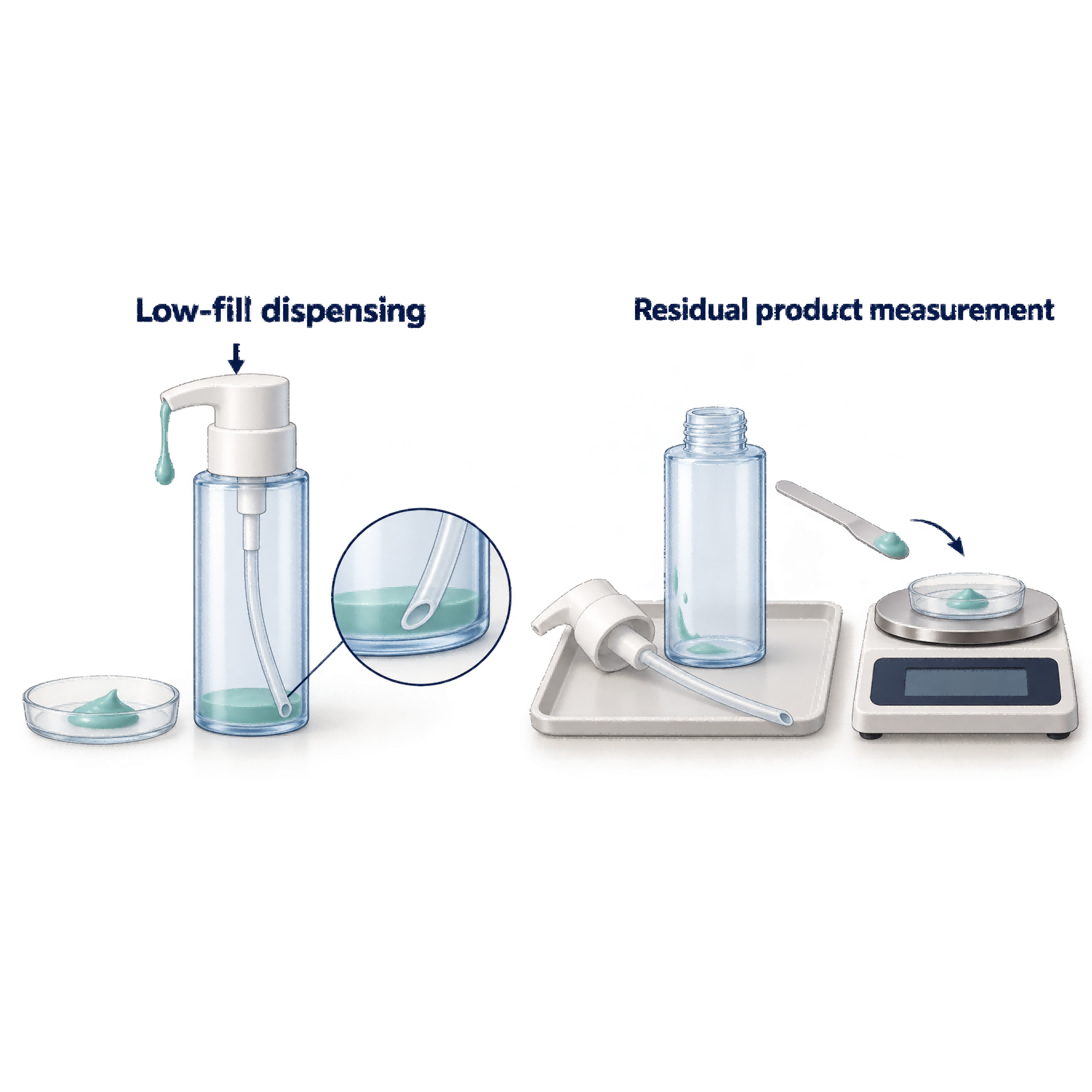
A full-bottle dispensing check cannot establish low-fill pickup performance. Approve the tube using the actual formula, intended bottle, pump, and production-representative closure assembly.
Agree on a trial plan that includes:
- Assembly inspection: Confirm seating, tube attachment, and installed inlet position.
- Initial use: Record priming strokes and any interrupted pickup.
- Progressive dispensing: Check output and refill behavior at full, intermediate, and low fill levels under a defined pressing routine.
- Storage evaluation: Repeat agreed checks after relevant storage conditions; inspect tube condition and connection security.
- End-of-use assessment: Record when useful dispensing stops and measure the remaining formula.
Define the endpoint before comparing samples. For example, agree what constitutes an unsuccessful press and how repeated unsuccessful presses end the test. Document whether shaking or tilting is allowed, since those actions change the use conditions.
For a controlled gravimetric comparison, use:
Residual product (%) = remaining formula mass at the agreed endpoint ÷ initial formula fill mass × 100
Distinguish formula remaining in the bottle from formula retained in the complete pack. Use consistent weighing and recovery methods, and account for leakage or evaporation when relevant. This is a proposed comparison method, not a cited universal test standard.
A low residual percentage alone does not demonstrate a good pack. Consider it alongside dispensing consistency, effort, leakage, and the intended user routine. Set acceptance criteria with the project team rather than borrowing an unsupported industry-wide limit.
Put the Approved Dip Tube Specification in the RFQ
The request for quotation should allow the supplier to reproduce the evaluated assembly.
| Specification field | Information to include |
|---|---|
| Bottle and pump identity | Model numbers, neck/closure details, and drawing revisions |
| Length definition | Measurement reference, tip endpoint, units, and tolerance |
| Tube dimensions | ID, OD, and agreed dimensional tolerances |
| Material | Approved material designation, grade information, and documentation |
| Inlet geometry | Cut or notch drawing and cutting-quality criteria |
| Attachment and position | Insertion depth, retention requirements, and installed tube path |
| Validation | Formula version, trial conditions, endpoint, and acceptance criteria |
| Production control | Approved sample reference, inspection plan, and change notification requirements |
Also ask about order quantity, sample configuration, lead time, and responsibility for final cutting and assembly. If the bottle, pump connection, or tube material changes after approval, agree which checks must be repeated before production release.
Frequently Asked Questions
Can two bottles with the same capacity use the same dip tube?
Possibly, but capacity does not establish internal depth or base shape. Compare the assembly drawings and verify the inlet position in each bottle before sharing a specification.
Can a buyer trim a tube while evaluating samples?
A controlled trim can help explore length during development, as the Cary Company describes. Record the change and request production-representative samples with the agreed cut before approval. A hand-trimmed development sample does not establish production cutting quality.
Does this specification process apply to an airless bottle?
First confirm the dispensing architecture. Many piston-based airless packs move product toward the pump without a conventional full-length dip tube. Ask for the assembly drawing and evaluate the components used by that design rather than assuming every pump bottle requires this specification.
Request a Sample Configuration for Your Project
To discuss a dip tube configuration, contact Topfeelpack with the bottle drawing or selected model, pump requirements, formula characteristics, expected order quantity, and target market. Request confirmation of the proposed tube dimensions, material, end cut, and sample assembly. Use those samples to agree on dispensing and residual-product checks before approving the production specification.
Post time: Oct-15-2026
